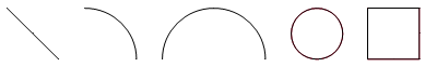
¼ Arc
½ Arc
Ellipse
Line
Rectangle
Rotate, Flip, Mirror and Re-size Graphic Objects
Changing Graphic Object Properties
Arc, Bezier Curve and Custom Shape Object Properties
Working with Bezier Curve and Custom Shape Objects
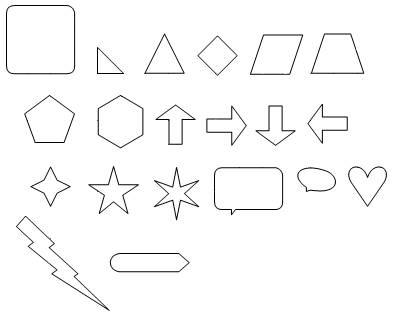
There is a wide assortment of purely graphic objects available, which can be quickly accessed in the Shapes tab of the ribbon control bar. These include the legacy objects that seasoned users will be familiar with:
|
|
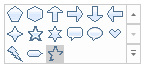
Beginning in PSCAD V5, multiple other predefined shapes are added as well:
|
|
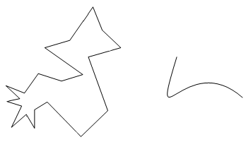
There are also two free-hand shapes:
|
Object properties, such as colour, fill and size can be changed to suit the component graphical needs. A good graphical design can enhance user understanding of the purpose of the component and what its primary function is.
Functional graphic objects include:
|
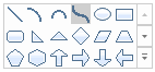
To add a graphic object to your component definition, the most straightforward method is to use the ribbon control bar Shapes tab:
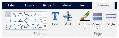
Depending on the object selected, a new object will appear attached to your mouse pointer. With your mouse, move the object to the desired location on the canvas and left-click to place the object.
Graphic objects can be rotated, flipped, mirrored or re-sized. To re-size, left-click on the object so that grips appear.
Place the mouse pointer over a selected grip, press and hold the left mouse button, and move the mouse. Note that the corner grips will allow re-sizing in both directions, while the mid-point grips will only allow movement in either the horizontal or vertical directions.
Rotate, flip or mirror can be accomplished in one of three ways. The first is to use the buttons in the ribbon control bar Shapes tab:

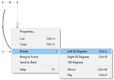
You can also use the right-click pop-up menus: Right-click over the object and select Rotate. Choose one of the options given.
As an alternative to the right-click menu and ribbon bar, you can also use keyboard shortcuts Ctrl + r, Ctrl + f and Ctrl + m (or simply r, f and m) for rotate, flip and mirror respectively. Make sure that the mouse pointer is over top the object before using these keys. If you select the object first, then the object will rotate, flip and mirror centred on the object itself.
Use the arrow keys on the keyboard to nudge objects (i.e. move them in small increments in a specific direction). Nudging objects is a great help when aligning multiple objects neatly.
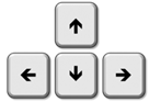
Select the component, then press one of the four arrow keys to nudge it along.
Graphic object properties can be adjusted through their corresponding Properties dialog. To change the object properties, either left double-click or right-click over the object and select Properties....
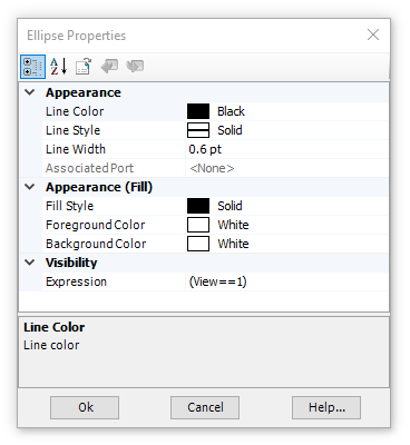
As shown above, graphical features such as styles and colours can be adjusted.
Appearance:
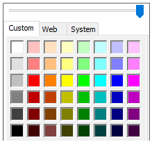
Line Colour: Select the down arrow to bring up the colour palette. Left-click on a colour box to change the line (or border) colour. Note the slider bar across the top can be used to adjust the opaqueness of the colour.
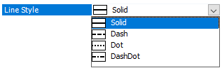
Line Style: Select the down arrow to bring up the line style list. Left-click on a style to change the line (or border) style.
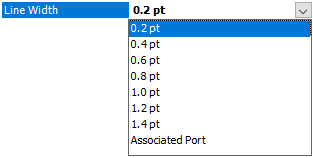
Line Width: Select the down arrow to bring up the line width list. Left-click on a width to change the line (or border) width. If Associated Port is selected, the type of port to which the object is associated with will determine the line width. See Port Connections for more details.
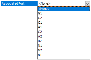
Associated Port: Select the down arrow to bring up the list of available ports. Left-click on a port to associate the line width setting to that port. This property is used to associate the line width with a specific local port connection. If the dimension of the port is greater than 1 (i.e. an array), then its line weight is doubled. This method is used extensively in master library components for single-line diagram compatibility. See Port Connections for more details. Note that the Line Width setting must be set to Associated Port to enable this field.
Appearance (Fill):
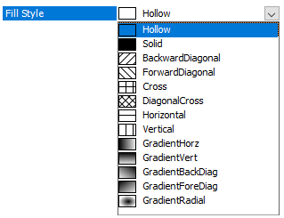
Fill Style: Select the down arrow to bring up the fill style list. Left-click on a fill style to change the object style.
Foreground Colour: Select the down arrow to bring up the colour palette. Left-click on a colour box to change the foreground fill colour. Note the slider bar across the top can be used to adjust the opaqueness of the colour.
Background Colour: Select the down arrow to bring up the colour palette. Left-click on a colour box to change the background fill colour. Note the slider bar across the top can be used to adjust the opaqueness of the colour.
Visibility:
Expression: Enter an expression to determine under what input conditions the object is to be visible. See Graphic Filters and Transparencies for more details.
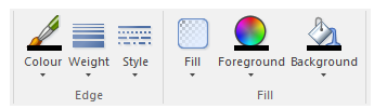
In addition to the Format Graphic Object dialog, you can change the line/border colour, weight and style, as well as fill properties directly from the ribbon control bar Shapes tab. First, select the object with a left-click (grips appear). Then adjust any of the above properties by using the appropriate buttons.
The Arc, Bezier Curve and Custom Shape are special types of graphical object. These object properties can be adjusted through the corresponding Properties dialog. Right-click over the object (without selecting it) and select Properties....
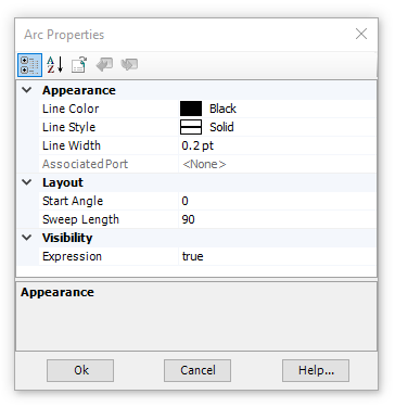
Layout:
Start Angle: Enter the angle in degrees at which the arc has its starting point. This angle is based on a standard, four-quadrant system.
Sweep Length: Enter the angular distance through which the arc is to sweep. Sweep distance is always in the counter-clockwise direction.
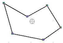
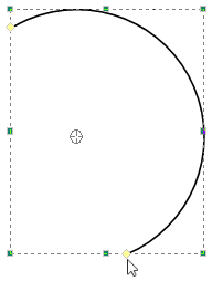
Start Angle and Sweep Length may also be adjusted graphically, by selecting the object with a left-click, then grab the yellow grips with the mouse pointer and adjust:
Orientation: Enter the orientation of the shape in degrees (Bezier Curve and Custom Shape only). This angle is based on a standard, four-quadrant system. Note that you must first Lock the shape before it can be rotated: Right-click on the shape and select Lock\Unlock to toggle lock status. See Working with Bezier Curve and Custom Shape Objects below.
Note all other properties are described above under Changing Graphic Object Properties.
The bezier curve and custom shape objects are more flexible than the others, and therefore possess some additional functionalities.
To create a custom shape, first click the Custom Shape icon in the ribbon control bar:
The graphic canvas will change to a pale yellow colour indicating that you are in Custom Shape Drawing Mode. Select the s key or simply left-click to start drawing a shape.
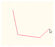
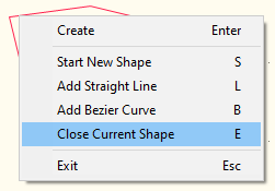
Continue drawing the shape by moving the mouse and either left-clicking, selecting the l key or right-clicking and selecting Add Straight Line, to define each line segment. Each line segment can be either a straight line or bezier curve. To add a bezier curve segment at any point, select the b key, Shift + left-click or right-click and select Add Bezier Curve.
When complete, select the e key, Alt + left-click or right-click and select Close Shape.
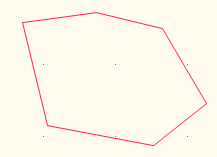
If finished, press the Enter key, Ctrl + left-click or right-click and select Create.
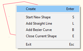
You may also close and create the shape in one step via Ctrl + Alt + left-click.
To exit Custom Shape Drawing Mode, select the Esc key or right-lick and select Exit.
Bezier curves are created in the same manner as any other graphic object. To create a bezier curve, click the Bezier Curve icon in the ribbon control bar:
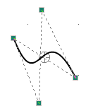
Note that both custom shapes and bezier curves can be adjusted after being created. Simply select the shape and grips will appear. Adjust the grips as required.